For most urban and suburban streets the optimal mounting height for solar street lights falls in the range 8–12 meters (26–39 feet) — this range balances even light distribution, required lumen output, glare control, and solar module placement for energy autonomy. Shorter poles (3–6 m) are better for parks, pathways and residential cul-de-sacs; taller poles (12–14 m or higher) suit multi-lane arterials and highways but increase luminaire power, structural and maintenance costs.
1. Why pole height matters for solar street lighting
Pole height is a design parameter that simultaneously affects optical performance, energy system sizing, civil works and lifecycle cost. Raising a luminaire increases the area a single fixture can illuminate, which can reduce the number of poles required, but it demands higher lumen output, larger solar arrays or batteries, and stronger pole structures. Conversely, lower poles deliver higher illuminance at ground level close to the fixture, improve visual comfort for pedestrians, and reduce required luminaire output, but they need closer spacing to achieve uniform coverage. These tradeoffs define the best practical height for any site.

2. Typical height ranges by application
Below is a concise table that synthesizes industry practice and municipal guidelines found in standard references and supplier engineering notes.
| Application / Road width | Typical pole height (meters) | Typical spacing (meters) | Typical luminaire class / comment |
|---|---|---|---|
| Pedestrian path / park (1–4 m width) | 3.0 – 4.5 | 8 – 15 | Low mounting, low glare |
| Residential local street (4–7 m) | 4.5 – 7.0 | 15 – 25 | Focus on uniformity and neighbor glare control |
| Collector / main city street (7–12 m) | 7.0 – 9.0 | 20 – 35 | Balance vehicle visibility and pole count |
| Wide urban road / multi-lane (12–20 m) | 8.0 – 12.0 | 30 – 45 | Typical for solar street lights in towns |
| Highways / expressways (>20 m) | 12.0 – 14.0+ | 40 – 60 | High pole, high lumen fixtures or mast arms |
| Sources: municipal design practice, supplier engineering notes. |
Key design note: Many municipalities and lighting handbooks list conventional mounting heights between 7.5 m and 15 m for urban roads and 25–50 ft (≈7.6–15.2 m) is common for local and collector streets. For special cases (freeway or large interchanges) heights may exceed this.
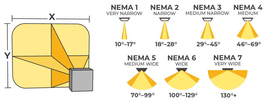
3. Light distribution, uniformity and the tradeoffs with height
Design goals usually include meeting a target horizontal illuminance (lux) and an acceptable uniformity ratio (average/minimum or Eave/Emin). Height influences both:
- Higher mounting creates wider, lower-intensity pools of light; uniformity tends to improve with appropriate optics and spacing but peak illuminance drops.
- Lower mounting yields higher peak lux directly beneath the fixture and can produce hot spots if spacing is too great.
- Glare and visual comfort: Taller mounts with proper cutoff optics reduce discomfort and skyglow per unit area, while low mounts may appear brighter to pedestrians and adjacent windows.
Because solar luminaires are limited by available wattage (battery and PV constraints), designers must match mounting height to available lumen packages to avoid under- or over-lighting. Many guidance documents note that shorter mounting heights produce better vertical illumination for pedestrian faces, which is desirable in parks and sidewalks.
4. Spacing rules and example calculations
A commonly used rule of thumb for approximate pole spacing is 2.5 to 3 times the pole height when uniform luminaires and consistent mounting are used. This rule helps set preliminary spacing before a detailed optical/lighting calculation is performed.
Quick examples (digit-by-digit arithmetic shown):
- If height = 6 m and spacing multiplier = 3.0 then spacing = 6 × 3.0 = 18 m.
- If height = 9 m and spacing multiplier = 2.5 then spacing = 9 × 2.5 = 22.5 m (round to design spacing, e.g., 22 m or 23 m).
- For a highway pole height of 12 m with multiplier 3.0 spacing = 12 × 3 = 36 m.
These are starting points. Final spacing and lumen output must follow a lighting calculation (IES LM-63 photometrics or equivalent) to meet target lux and uniformity. For axial symmetric layouts or staggered side placements the multiplier can be adjusted and spacing optimized using lighting software.
5. Solar-specific constraints that affect chosen height
Solar systems introduce extra considerations beyond those of grid-tied luminaires:
- Panel mounting and tilt: Solar panels require exposure to sun. Lower poles may place panels in shading from trees or buildings; higher poles allow panels to be mounted away from shade but increase wind load. Panel area grows as luminaire power and autonomy requirements increase.
- Battery & PV sizing: Taller poles that require higher lumen output will need larger PV arrays and batteries, which increases head-unit weight and foundation size, or requires a separate ground-mounted PV array.
- Maintenance access: Pole height affects how maintenance is performed. Ground-replaceable batteries or modular luminaire designs reduce the need for bucket trucks, which matters greatly in rural projects.
- Shading and microclimate: Trees, buildings, adjacent poles or even other panels can produce partial shading that dramatically reduces PV output. Lower height close to tree canopies is risky for solar yield.
Practical recommendation: When solar modules are integrated into the pole head, target a mounting height that allows unobstructed solar exposure between about 10:00 and 15:00 solar time for the majority of the year, or plan for ground-mounted panels where shading cannot be avoided.
6. Structural, wind and safety considerations for taller solar poles
Taller poles carry larger wind and bending moments, especially when PV panels are integrated in a non-streamlined fashion. Key structural checks include:
- Wind load calculations to the local wind code (ASCE 7, EN 1991-1-4 or local code).
- Foundation design sized for overturning moment and soil bearing; deeper or larger footings are common for >10 m poles.
- Vibration and resonance checks, especially with long slender poles and asymmetrical PV loads.
- Material and corrosion protection for coastal or industrial environments.
Procurement teams must specify design wind speed, exposure category, pole material (steel grades), hot-dip galvanizing or painting, and access features (hand hole, ladder, anchor points). Taller poles typically add 15–40% to civil and foundation cost vs shorter poles, depending on soil and seismic conditions.
7. Cost, lifecycle and maintenance impact
Height affects three long-term cost buckets:
- CapEx: taller poles often mean fewer fixtures per km but higher per-pole fabrication and foundation costs; solar PV and battery size may increase per pole.
- OpEx: maintenance access for higher poles may require specialized equipment; battery replacement cycles are driven more by battery chemistry and depth of discharge than by height, but larger batteries can be more expensive to replace.
- Energy yield and reliability: shallowly mounted panels with partial shade reduce energy yield, increasing risk of nighttime outages and battery cycling that shortens life.
A lifecycle view often favors using moderate heights (8–12 m) for public streets where a single supplier can balance luminaire optics, PV size and civil works. For parks and pedestrian paths, 3–5 m poles minimize cabling and civil work even if more poles are needed.
8. Procurement specification checklist (table)
Use the table below when preparing a tender or internal technical spec for solar street lighting procurement.
| Section | Minimum content to specify |
|---|---|
| Project summary | Road classification, width, traffic characteristics, luminaire mounting layout (one-side, staggered, central), target lux and uniformity |
| Mounting height | Exact nominal height(s) in meters; tolerances (±0.1 m) |
| Lighting performance | Target horizontal illuminance (lux), maintained illuminance, uniformity ratio (avg/min) |
| Photometrics | Manufacturer LM-79/LM-63 files for candidate luminaires; beam type and tilt |
| Solar system | PV power (W) per pole, panel tilt/azimuth, battery type and Ah, autonomy days |
| Structural | Wind speed design basis, pole material/grade, foundation type and details |
| Maintenance | Access method, expected lifetime (20+ years pole, 5–10 years battery), replacement policy |
| Testing & certification | CE/UL, IP/IK ratings, Salt spray if coastal, warranty |
| Data & monitoring | Remote telemetry/GSM reporting (optional), energy logging |
| This checklist helps align procurement teams and engineers on the single most impactful parameter: mounting height. |
9. Example design scenarios with simple calculations
All arithmetic shown step-by-step.
Scenario A: Residential street, 6 m carriageway, target average 10 lux
- Choose pole height = 6 m (common for local streets).
- Spacing multiplier = 3.0 → spacing = 6 × 3.0 = 18 m.
- If road length = 360 m, required poles = 360 ÷ 18 = 20 poles.
- If luminaire delivered flux per fixture must produce 10 lux average over target roadway width, photometric calculation is required but initial design uses a mid-range LED 6,000 lm fixture with asymmetric lens.
Scenario B: Urban collector, 10 m carriageway, target average 15 lux
- Choose pole height = 9 m (midpoint of 7–9 m).
- Spacing multiplier = 2.5 → spacing = 9 × 2.5 = 22.5 m (round to 22 m for practical mounting).
- If road length = 450 m, required poles = 450 ÷ 22 = 20.45 → specify 21 poles.
These samples illustrate how height sets spacing and pole count, which in turn link to total PV and battery needs. Detailed photometric and energy calculations are required before procurement.
10. Practical recommendations for engineers and procurement teams
- Start with application classification: pedestrian, residential, collector, arterial, highway. Match that to the table in section 2.
- Use the 2.5–3× height spacing rule for preliminary layout; refine using IES/EN photometric calculations.
- Avoid integrated PV panels that face toward likely shade; if trees are present consider ground-mounted arrays.
- Specify design wind speed and local codes in the tender; taller poles require verified foundation designs.
- Balance CapEx vs OpEx: fewer taller poles can reduce unit cost for luminaires but increase foundation and maintenance costs. Run a life-cycle cost model.
11. Two short case studies
Case study 1: Small town retrofit
A small town replaced old sodium luminaires with solar LED heads on existing 9 m poles. Because poles already existed and were sited, the solar modules were ground-mounted near clusters to avoid adding weight to poles. Result: lower civil cost, simpler maintenance, but higher cable runs.
Case study 2: New highway segment
A highway project selected 12 m mast arms with asymmetric high-output LEDs and pole-top PV installations. Foundation cost rose by 30% over local streets, and PV and battery per pole were substantially bigger, but spacing of 36–40 m reduced pole count and expedited installation.
12. Common mistakes and how to avoid them
- Selecting height first, then ignoring solar exposure: always verify solar access before fixing height.
- Over-reliance on rule-of-thumb spacing: use lighting software for final verification.
- Under-specifying wind load: always provide local design wind speed and exposure to suppliers.
13. Glossary of key terms
- Mounting height: vertical distance from finished grade to the lamp centerline.
- Uniformity ratio: measure of evenness of illumination; common forms are Eavg/Emin.
- IES photometrics: industry data format for luminaire light distribution.
- Autonomy: number of nights a system will operate without recharging.
14. Appendix: Recommended quick reference (tables)
Table A . Road width to recommended mounting (metric)
| Road width (m) | Recommended mounting (m) | Preliminary spacing (m) |
|---|---|---|
| 1–4 | 3–4 | 8–12 |
| 4–7 | 4.5–7 | 12–25 |
| 7–12 | 7–9 | 20–35 |
| 12–20 | 8–12 | 30–45 |
| >20 | 12–14+ | 36–60 |
| Sources: synthesis of municipal handbooks and supplier engineering guidelines. |
Table B. Height tradeoffs
| Height band | Advantages | Disadvantages |
|---|---|---|
| 3–5 m | Good pedestrian face illumination, low foundation costs | Requires many poles, can cause glare near windows |
| 6–9 m | Good balance for residential and collector streets | Moderate PV size if solar integrated |
| 10–14 m | Wide coverage, fewer poles | Higher luminaire power, larger foundations, higher maintenance cost |
15. FAQs
- Q: Is there a single “best” height for all solar street lights?
A: No. Best height depends on application, road width, target lux and solar exposure. For general urban use 8–12 m is often optimal; pedestrian paths typically use 3–5 m. - Q: Can I place larger PV panels on a short pole?
A: You can, but short poles are more likely to be shaded and impose awkward tilt angles. Ground-mounted arrays or dedicated rack at pole base are often better for large PV needs. - Q: What spacing should I use as a starting point?
A: Use 2.5–3× the pole height as a preliminary spacing; refine using photometric models. - Q: How does height change maintenance cost?
A: Taller poles usually raise maintenance costs because specialized lifting equipment is often required; but fewer poles can reduce routine visits per km. Balance is project specific. - Q: Do standards mandate specific mounting heights?
A: Standards provide guidance but municipalities set final heights. Many municipal handbooks give ranges (e.g., 25–50 ft for conventional streets). Refer to local codes and FHWA or municipal design manuals. - Q: How to validate a chosen height?
A: Produce photometric simulations using manufacturer LM-79/LM-63 files and verify target lux and uniformity at the proposed height and spacing. Field trials or pilot sections are recommended for large projects. - Q: Are integrated pole-top solar heads always best?
A: Not always. Integrated heads simplify cabling but can complicate PV orientation, shade and service. For high energy demands separate ground PV arrays may be better. - Q: What wind code or structural specs should I include?
A: Specify the applicable wind speed (e.g., per ASCE 7 or local code), exposure class, seismic basis if relevant, pole material and treatment, and require certified calculations for poles taller than 10 m.
16. How SunplusPro can help your project
If your project is buying solar street lights, SunplusPro can provide: tailored photometric layouts at proposed mounting heights, integrated or separate PV options, structural drawings with local wind assumptions, and lifecycle cost comparisons for alternative mounting heights. Provide your road class, width and desired maintained lux and we will return a price and technical layout.
17. Final checklist before signing a PO
- Confirm target lux and uniformity and capture them in contract.
- Lock mounting heights with acceptable tolerances.
- Require LM-79 / LM-63 photometric data for each luminaire offered.
- Specify PV access/tilt and shading study acceptance thresholds.
- Require structural calculations stamped by a licensed engineer for poles ≥10 m.
- Include a clause on as-built verification and a short pilot run.